Anti-Aliasing.com
Aliasing & Anti-Aliasing in CGI
By Michel A Rohner
Images generated by computer consist of two-dimensional arrays of pixels (picture elements),where each pixel can have only a single color. In computer generated imagery (CGI), the scenes rendered by computer consists of object made of many triangles that are projected onto the image. When a pixel is completely covered by a triangle, it is painted with that triangle color. When more than 1 triangles cover a portion of a pixel, a decision has to be made about which triangle color to select. The simplest solution is to use the color of the triangle at the center of the pixel. This is referred to as single point sampling. When images are rendered by computer using single point sampling, they can achieve the fastest processing time, at the expense of aliasing artifacts, or “jaggies”. The most noticeable artifacts are “stairsteps” and “narrow faces breakup”. In moving images, stairsteps result in “crawling“ and narrow faces breakup result in “faces popping in-and-out of scenes”. Anti-aliasing techniques refer to the methods used to minimize these distracting artifacts.
The current anti-aliasing approaches consist on doing more processing to correct aliasing artifacts caused by single point-sampling. They can reduce stairsteps and crawling. However, they are doing a poor job at correcting narrow faces breakup. There is an urgent need for a new and more efficient approach that can produce images without aliasing artifacts.
Area-Based anti-aliasing (ABAA), is a new approach based on area sampling instead of point sampling. With ABAA, the pixel is divided into N subpixel areas of equal size, instead of N discrete points. ABBA is the best at handling stairsteps and narrow faces breakup, regardless of polygon edge orientation. ABAA is faster and produces the best images with anti-aliasing. Currently, there is no readily available product using ABAA. But simulations have shown that ABAA is the best anti-aliasing solution.
Among the current approaches, Multi-Sample anti-aliasing (MSAA) is the most commonly used. It has been around for around 40 years. However, it is slow and does a poor job at handling narrow faces breakup. With MSAA, images are computed for 4 (or 8) subpixel sample points, followed by averaging. The frame rate is reduced by a factor of 4 (or 8), making too slow for demanding RT CGI applications. It works well for horizontal and vertical edges. For other edge angles, the larger gaps between subpixels can cause narrow face breakups.
In order to improve the frame rate, several methods rely on single point sampling followed by image post-processing, with mixed results. Among these are: Fast Approximate Anti-Aliasing (FXAA), Temporal Anti-Aliasing (TAA) and Morphological anti-aliasing (MLAA).
Computer Generated Imagery
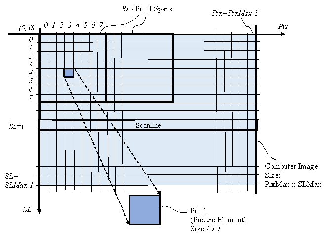
CGI consists of computer applications for creating images in art, printed media, video games, simulators and computer animation. These images consist of 2 dimensional arrays of pixels (picture elements) of size 1920x 1080 pixels for example. Refer to Figure 1. During image computation, images are temporarily stored in face buffers consisting of Color-buffers and Z-buffers.

Aliasing Artifacts
In CGI, television and movies, aliasing is also referred to as distracting artifacts, or jaggies. Among them: stairsteps, edge crawling, narrow faces breakup, face popping and Moiré patterns. The purpose of anti-aliasing is to minimize these distracting artifacts.
Single Point Sample (No Anti-Aliasing)
In CGI, the 2D images can be projections of 3D objects. When these images are computed with a single sample point per pixel, they show distracting artifacts. In static images, these artifacts consist of “stairsteps” and “narrow faces breakup”. In dynamic scenes stairsteps result in “crawling” and narrow faces breakup result in “faces popping in-and-out of acene”.
Edge Stairsteps and Crawling
In static images, rendering with single point sampling results in “stairsteps” on face edges.
In dynamic scenes, aliasing artifacts are amplified, resulting in edge “crawling” Refer to Figure 2.

Narrow Face Breakup
Most anti-aliasing methods can do a decent job in reducing stairsteps and crawling for faces larger than 1 pixel wide. However, when faces get narrower than 1 pixel wide, they do a poor job in reducing narrow face breakup. Refer to Figure 3.

Face popping
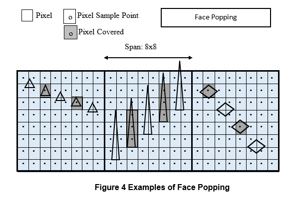
Face popping is a temporal artifact. It consists of objects going in-and-out of scenes when some dimensions of displayed polygon faces are smaller than the pixel size.
In Figure 4 there are examples of face popping. These tiny faces are displayed only when the pixel sample point is inside of the faces. In moving scenes, this results in face popping in-and-out of scenes.

Z-Buffer (or Depth-Buffer)
In 3D space, objects are made of many triangular faces. When these triangles are projected onto a 2D image, points in 3D space with coordinate V=(x, y, z) end up with 2D image coordinates V=i(xi, yi), where:
xi=x/z; yi=y/z
3D Distance Coordinate z and Depth in Image Coordinate zi:
The projected image is on a plane at distance z==1 from the viewpoint. So, each point in 3D space can be considered to be on a 4-components coordinate system V=((x, y, z,1).
After projection, the vector V is projected onto a 2D vector Vi in the projection plane (image):
Vi = V/z = (x/z, y/z, z/z, 1/z) = (xi, yi, 1, zi), where zi = 1/z
The projected vector has a 2D coordinate (xi, yi) on the image plane and is also associated with a depth coordinate represented by zi=1/z. Or:
Vi=(xi, yi, zi)
Since the coordinate V=(x, y, z) is linear in the 3D space, Vi=(xi, yi, zi) is also linear in the 2D space. As a consequence:
The depth coordinate zi linear in the 2D space (image), while the distance z (from 3D space) is non-linear in the 2D space. On the other hand, the distance z cannot be linearly interpolated in the projected space…
Depth Coordinate zi:
The depth coordinate zi is linear in image coordinates and can be interpolated.
The image depth coordinate, zi, is used to determine which triangle is in front of another. During the image computation, the image is stored into 2 types of image buffers:
Color-Buffer and Z-Buffer.
The color components (R, G, B) of the closest face (with max zi) are stored in the Color-Buffer and the depth coordinate zi is stored in the Z-Buffer. For the Color, there is a double buffer: one to build the image and one to display the previously computed image.
When 2 triangles are too close in depth, aliasing might result, when there is not enough depth accuracy to determine which one is the closest.
Definitions from Wikipedia
Refer to definitions for Aliasing, Jaggies, Moiré Pattern from Wikipedia and Internet
Aliasing: https://en.wikipedia.org/wiki/Aliasing
Jaggies: https://en.wikipedia.org/wiki/Jaggies
Moiré Pattern: https://en.wikipedia.org/wiki/Moir%C3%A9_pattern
Z-Buffer or Depth-Buffer https://www.geeksforgeeks.org/z-buffer-depth-buffer-method/
Anti-Aliasing in CGI
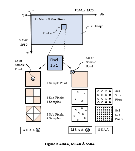
Aliasing artifacts can be minimized by applying anti-aliasing techniques. Several anti-aliasing approaches are presented here. Refer to Figure 5.
Most anti-aliasing methods that rely on point sampling can do a decent job in reducing stairsteps and crawling for faces larger than 1 pixel wide. But there is a serious limitation when faces get narrower than 1 pixel wide. They do a poor job at eliminating narrow face breakup.
Area-Based anti-aliasing (ABAA) is a new approach that does not have these limitations. It uses subpixel area sampling instead of point sampling. It can produce high image quality without the speed penalty.
Among the prior art for anti-aliasing are two methods that rely on computing multiple images, followed by averaging: Super-Sampling anti-aliasing (SSAA) and Multiple-Sample anti-aliasing (MSAA). Although these methods produce good images, they are time consuming. MSAA is faster, since it uses fewer sample points. It can be speeded up by using more processing power, thus increasing the system cost.
To improve the frame rate, many approaches build an image with point sampling, followed by image post processing.

References:
Anti-Aliasing: https://vr.arvilab.com/blog/anti-aliasing
What is anti-aliasing? TAA, FXAA, DLAA, and more explained:
https://www.digitaltrends.com/computing/what-is-anti-aliasing/
What is Anti-Aliasing? Ultimate Guide:
https://www.selecthub.com/resources/what-is-anti-aliasing/
Area-based Anti-Aliasing (ABAA)
With ABAA, the pixel is divided into N subpixel areas of equal size. instead of N discrete points. For each triangle edge, the covered area assigned to subpixel areas is equal to the actual covered area, to the closest digit. The process consists of detecting which pixels are intersected by polygon edges. At the same time, the covered area inside of these pixels is obtained with a single measurement. It is measured at the intersection of edges with a midline inside the pixel.
Most of the other anti-aliasing solutions rely on “point sampling” followed with post processing. They are a compromise between speed and image quality. Anti-aliasing is accomplished by blurring adjacent pixels that have high color contrast. They are a compromise between speed and image quality.
Subpixel Area Sampling
The area-based approach solves several problems.
- ABAA can quickly determine the covered area in intersected pixels and compute the mixed colors.
- It produces equal steps as triangle edges move across pixels, for all edge-orientations. The covered area of pixels increases uniformly (linearly) from 0.0 to 1.0 as edges move across pixels.
- With 4 (or 8) subpixels It can handle narrow face breakup for faces wider than 1/4 (or 1/8) pixel wide.
- It can produce high image quality without speed penalty. It is faster since is does not require multiple frame processing.
Currently, there is no readily available product using ABAA. But simulations have shown that ABAA is the fastest anti-aliasing solution that also produces the best images with anti-aliasing, without postprocessing. During rendering, edges efficiently traverse the image from pixel to pixel. Intersected pixels are easily identified. The partially covered area of pixels, that is used for color mix, is readily available in 1 measurement (no lengthy computations). ABAA can be implemented directly using pixel covered areas, or the area can be mapped into 4, 8, 16 or 32 subpixel areas.
The ABAA method and the subpixel areas mapping is described in more detail in a set of books from M. A. Rohner. There are 3 versions of the book, from introduction to extended versions:
- “Introduction to Area-Based Anti-Aliasing for CGI”, Michel A. Rohner, Gotham Books Inc 2024-05-15, 194 pages (short version).
- “Anti-Aliasing with ABAA vs MSAA”, Michel A. Rohner, Gotham Books Inc 2024-03-15, 272 pages (compact version).
- “New Area-Based Anti-Aliasing for CGI”, Michel A. Rohner, Gotham Books Inc 2024-03-15, 351 pages (extended version).
Detect Intersected Pixels with ABAA
Most approaches use sample points to detect when a portion of the triangle covers the pixel.
With ABAA, intersected pixels are identified as follows. The rendering operation is optimized with 2 types of edges, according to their slopes.
- Horizontal edges (HE), when edge slope |dy/dx| < 1.0.
- Vertical edges (VE), otherwise.
When edges traverse the image from pixel to pixel, the intersected pixels are easily identified. A pixel is partially covered by a triangle edge, when that edge intersects a midline inside of that pixel. At the same time, the partially covered area of that pixel, that is used for color mix, is readily available in one measurement (no lengthy computations).
Note that:
- With ABAA, a pixel is considered intersected only when the edge intersects a midline inside of that pixel. It does not matter if the trapezoid extends partially into an adjacent pixel. It does not matter if the edge intersects a pixel near a corner without intersecting a midline.
- This intersection on the midline is where the covered area is measured.
ABAA can be implemented directly using pixel covered areas, or the area can be mapped into 4, 8, 16 or 32 subpixel areas.
In Figure 6, there are two examples of a pixel intersected by a triangle edge.
- ABAA 4: Pixel with 4 subpixel areas intersected by a VE.
- ABAA 8: Pixel with 8 subpixel areas intersected by an HE.
ABAA detects the intersected pixels and evaluates the partially covered area inside of these pixels in one step.
When a pixel is intersected by a triangle edge, that edge divides the pixels into 2 trapezoids. Since the height of the trapezoid is 1.0, the areas of these trapezoids are equal to the average of their top width and bottom width. These areas can be measured on a midline, half-way from the top and bottom of the trapezoid. They are determined by the intersection of the triangle edge with one of two midlines inside of the pixel: H-midline for VE or V-midline for HE.
With ABAA, a pixel is considered intersected only when the edge intersects the midline inside of that pixel. It does not matter if the trapezoid extends partially into an adjacent pixel. It does not matter if the edge intersects a pixel near a corner without intersecting a midline.
For a VE, use the H-midline. This is the case for the top example with 4 subpixels.
For an HE, use the V-midline. This is the case for the bottom example with 8 subpixels.
Note that even when the trapezoid extends outside the pixel boundary, the measured area is still correct. As edges move across pixels, the covered area transitions from non-covered to fully covered in equal steps, from 0.0 to 1.0. This method is very accurate. With 4 fractional bits, there can be 16 equal steps. The pixel color of intersected pixels is a weighted mix according to the 2 areas.
There can be 2 approaches when implementing ABAA:
1. Use the measured areas to mix the colors of the 2 partial areas in the pixel. This approach works well when there are only 2 fragments in a pixel. When there are more fragments, this approach produces acceptable results.
2. Assign the area covered by edges into subpixel areas (4, 6, 16 or 32). This approach is better when there are more than 2 fragments in a pixel. The mapping of the pixel covered area into subpixel area is described in the books.
Ther are 2 ways to computes the color mix. The color mix can be calculated either by using the partially covered area, or by using the covered subpixel counts.

Update Pixels with Partially Covered Area
In the simplest implementation, when an intersected pixel is encountered, the old pixel is retrieved from the Color buffer. If the depth of the new triangle is closer (with larger zi), the color of the retrieved pixel is updated according to the area partially covered by the new edge. The zi is also updated. There are different cases for beginning edges (BE) ending edges (!BE) and internal edges (IE).
There can be many ways to implement this solution. One solution would be to use two z buffers: one for the top face and one for the next top face. There can be several cases when there is more than one edge in a pixel. When there is another edge in the pixel, the new covered area is blended with the previous color mix. The new partial color is always mixed with the previous mix. The color error is negligeable, because it is attenuated by the new edge. This is comparable to a “moving average”.
This approach should produce more accurate and sharper images when compared with post processing methods that blend adjacent pixels that are identified from their high contrast.
Assign Subpixel Areas to 4 or 8 Subpixels
ABAA is Simpler and Faster
SSAA and MSAA: Subpixel Point Samples
Two commonly used anti-aliasing methods rely on multiple sample points: Super-Sampling anti-aliasing (SSAA) and Multi-Sample anti-aliasing (MSAA). These techniques are more time consuming than single sample point, since they require rendering of several images, followed by image averaging.
Super Sampling Anti-Aliasing (SSAA)
The SSAA approach has been used in non-real-time applications. In this approach, a 512×512 image is first computed at higher resolution, such as 2048×2048, for example. It is then reduced through averaging or filtering to produce a 512×512 image. It is computation intensive and cannot be used for RT CGI applications. Since there are no time constraints, large images can be computed offline using high-speed general-purpose computers.
Multi-Sample Anti-Aliasing (MSAA)
For RT CGI applications, algorithms are limited to methods that can produce new images at rate of at least 60 frames per second. It is the most used approach to subpixel processing in RT. With MSAA, several images are computed for 4 or 8 sample points (or subpixels) inside of pixels, followed by images averaging.
MSAA can do a decent job in reducing stairsteps and crawling for faces larger than 1 pixel wide. But it does a poor job at reducing narrow face When faces get narrower than ½ pixel wide, breakup.
8-Queens Puzzle
The position of the subpixel sample points can be derived from solutions to the “8-queens-puzzle”. The solutions to the 8-queens puzzle provide good results for near horizontal and vertical edges. But the anti-aliasing effectiveness is not as good for edges with angles in-between. On the other hand, the ABAA solution works consistently for all angles.
MSAA with Edges Gaps at 0 Degrees and 30 Degrees
Fig. 7 illustrates the main limitation of point sampling used by MSAA. The main problem is that there are many cases where 2 or more sampling points line up with the triangle edges. This reduces the number of transitions as edges move across pixels There are 2 extrema cases.
- The two examples on the left side illustrate the best cases with horizontal (HE) and vertical (VE) edges at 0 degrees angle. In these cases, there are 4 (or 8) transitions as edges move across 4 (or 8) sample points.
- The two examples on the right side illustrate the worst cases with edges at roughly 30 degrees angle. In these cases, there can be only 2 (or 3) transitions as edges move across 4 (or 8) sample points. The larger gaps between edge transitions can cause narrow face breakups for face narrower than ½ pixel wide.

MSAA vs ABAA
MSAA has been around for around 40 years. While it is relatively slow (computation intensive) and costly, it is considered as the best current approach for image quality using point sampling.
ABAA relies on area sampling and does not have the limitations of point sampling. It does a better job with narrow faces. The ABAA solution produces more consistent results than SSAA or MSAA, at lower cost and lower power. Using the same number of subpixels, it produces better image quality than MSAA.
Post-Process Anti-Aliasing
Since MSAA is slow, several methods use faster approaches by rendering images in 2 steps. They compute an image using 1 sample point per pixel, followed by blurring pixels with postprocessing. Some use GPUs to detect edges of a polygon by comparing color contrasts between two adjacent pixels. When both pixels are similar, it is assumed that they’re from the same polygon.
One advantage of this approach is that it can be faster than MSAA. A significant disadvantage is that they make the image blurrier. This can negatively affect games with detailed features.
Fast Approximate Anti-Aliasing (FXAA)
Fast approximate anti-aliasing (FXAA) is a screen-space anti-aliasing algorithm created by Timothy Lottes at Nvidia. It is a single-pass, screen-space anti-aliasing technique designed for producing high-quality images with low performance impact. FXAA uses only 1 sample point per pixel. It achieves anti-aliasing using a post process to clean up jagged edges. This requires much less processing than MSAA and SSAA, though at the cost of image quality.
Temporal Anti-Aliasing (TAA)
Temporal Anti-Aliasing (TAA) uses a post process similar to FXAA. However, it samples a different location within each frame. It uses past frames to blend the samples together.
Morphological Anti-Aliasing (MLAA)
Morphological Antialiasing (MLAA) is a post process filtering similar to FXAA. It detects borders in the resulting image and also looks for specific patterns. Then it blends pixels in these borders, according to the pattern they belong to and their position within the pattern. It should be slower than FSAA.
Enhanced Subpixel Morphological Anti-Aliasing (SMAA)
Subpixel Morphological Anti-Aliasing (SMAA) is also similar to FXAA. It uses edge detection and blurs pixels around harsh edges. The main difference is that SMAA relies on taking multiple samples along those edges. Developed by Jorge Jimenez, a student from the Universidad de Zaragoza, SMAA combines post-process and spatial anti-aliasing to create an image. The images it creates are of higher quality than those produced by FXAA and MLAA.
Deep Learning Super Sampling (DLSS)
Deep learning super sampling (DLSS) is a family of real-time deep learning image enhancement and upscaling technologies developed by Nvidia that are available in a number of video games. The goal of these technologies is to allow the majority of the graphics pipeline to run at a lower resolution for increased performance, and then infer a higher resolution image from this that approximates the same level of detail as if the image had been rendered at this higher resolution. This allows for higher graphical settings and/or frame rates for a given output resolution, depending on user preference. (from Wikipedia)
Definitions from Wikipedia and Internet
Refer to definitions for SSAA, Spatial Anti-Aliasing, TAA, MSAA, MLAA, SMAA and 8-Queens Puzzle from Wikipedia.
FXAA: https://blog.codinghorror.com/fast-approximate-anti-aliasing-fxaa
ABAA: https://en.wikipedia.org/wiki/Area-based_anti-aliasing
TAA: https://en.wikipedia.org/wiki/Temporal_anti-aliasing
SSAA: https://en.wikipedia.org/wiki/Supersampling
Spatial AA: https://en.wikipedia.org/wiki/Spatial_anti-aliasing
MSAA: https://en.wikipedia.org/wiki/Multisample_anti-aliasing
MLAA: https://en.wikipedia.org/wiki/Morphological_antialiasing
SMAA: https://github.com/iryoku/smaa
DLSS https://en.wikipedia.org/wiki/Deep_learning_super_sampling
8-Queens Puzzle: https://en.wikipedia.org/wiki/Eight_queens_puzzle
Moving Average https://en.wikipedia.org/wiki/Moving_average